 Business License

UV Curing of Lithium Battery Electrode Protective Coatings: A Process Guide for Roll-to-Roll Production
Why Protective Coatings Became Part of the Cell
Modern lithium-ion cells are pushed toward higher nickel content, higher energy density, and faster charging, and each of those targets puts stress on the interfaces inside the cell. High-nickel cathodes release transition metal at elevated voltage and temperature. Graphite and silicon anodes change volume during cycling, which stresses the surface layer. Separators can shrink at elevated temperature, creating a path for internal shorting. Electrolyte oxidation at the cathode surface generates gas and raises impedance over the life of the cell.
Protective coatings are the engineering response to those interface problems. A thin layer on the cathode surface, the anode surface, the separator, or the current collector binds active material, blocks side reactions, limits transition metal dissolution, and stabilizes the solid-electrolyte interphase. The coating is invisible in the finished cell, and its quality is measured in cycling life, gas generation, and impedance rather than in appearance.
This article examines how ultraviolet curing, delivered through a UV LED curing lamp, fits this production step, what it requires on a roll-to-roll coating line, and where the process commonly goes wrong. It is written for coating process engineers, cell R&D teams, separator and electrode coating contractors, and equipment specifiers evaluating a UV step for a battery production line.
Where UV Coatings Appear in the Battery Stack
Protective coatings in a cell fall into a few distinct categories, and each places a different demand on the cure.
Cathode protective coating. A thin polymer or polymer-ceramic layer over the high-nickel or LFP active material reduces electrolyte oxidation and transition metal release during cycling. The coating must remain ionic-permeable and stable at cathode voltage, and it must not form an electrically insulating barrier that raises internal resistance.
Anode protective coating. A layer over graphite or silicon-composite anode stabilizes the SEI and cushions volume change. It must flex with the expanding particle and remain bonded after repeated cycling.
Separator coating. A ceramic or polymer-ceramic layer on a porous polyolefin or polyethylene separator raises thermal stability, reduces shrinkage, and improves insulation at high temperature. This is the application where temperature control during cure matters most, because the base film itself is heat-sensitive.
Collector and primer coating. Thin conductive or adhesion-improving layers on aluminium and copper foil improve the bond between active material and collector and reduce contact resistance over time.
Ultraviolet-curable binders appear across these categories wherever the line needs a fast, in-line cure with low thermal input and little volatile residue. They are not a replacement for every coating system, but they have a specific role where thermal drying is constrained or where residual species in the cell are a liability.
The Roll-to-Roll Coating Line Sets the Rules
Battery protective coatings are applied on continuous web lines, not on discrete parts, and the line geometry defines most of the curing parameters.
Web speed sets exposure time, and a UV LED curing lamp on the line has to hold rated irradiance across that dwell rather than only at a stop A coating line running tens of metres per minute gives the wet film a fraction of a second under the curing station, so the required irradiance and dose are calculated against that dwell rather than against a static cure time.
Web width sets the uniformity requirement. A coating band across a one- or two-metre web must receive consistent energy from edge to edge, because a low-dose region becomes a local under-cure that shows up later as uneven impedance or gas. Centre-only irradiance readings are not adequate on a wide web.
Tension and handling define the working distance and the head mounting. The web may sag, wander, or vibrate under tension, and the curing head has to hold a stable distance from a moving surface rather than from a fixed coupon. Gap control and edge clearance are part of the line design, not an installation afterthought.
The wet film itself is thin. Protective coating dry layers are measured in micrometres, which works in favour of cure penetration but demands precise dose control: too little energy leaves residual binder, too much embrittles a layer that has to survive winding and cycling.
The Chemistry Behind the Cure
A UV-curable protective coating is a mixture of polymerizable binder, photoinitiator, solvent or water carrier where applicable, and usually a high loading of ceramic filler such as alumina, boehmite, or zirconia particles.
The binder is the component the ultraviolet reaction sets. Acrylate and epoxy-based systems are common, chosen for adhesion to the substrate, flexibility after cure, and electrochemical stability in the electrolyte. The photoinitiator package defines the wavelength band the coating responds to, and that band has to match the curing source.
The filler does not absorb ultraviolet the way a pigment does, but it scatters it. Ceramic particles in a loaded film redirect and attenuate the light passing through, which changes how much energy reaches the binder at the bottom of the coating. Fillers also make the film opaque and physically rough, which affects adhesion and how the film survives bending.
Residual chemistry is the central risk in this application. Unreacted monomer, oligomer, or photoinitiator left in an under-cured film can migrate into the electrolyte, react at the electrode, poison the SEI, increase impedance, or contribute to gas generation. This is why cure completeness in a battery coating has a direct electrochemical consequence, unlike in most decorative or structural applications.
Why Thermal Cure Is a Constraint Here
Conventional protective coatings are dried and cured thermally in a long oven section. That works, but it imposes costs the coating line has to carry.
The most serious constraint is temperature on the substrate. Polyolefin separators soften and shrink well below the temperatures some thermal processes reach, and an oven profile that dries the coating evenly may push the film toward its dimensional limit. Porous electrodes and thin foils also carry temperature-sensitive binders and active material that should not see repeated high heat.
Thermal drying also occupies line length. An oven section for water-based or solvent-based slurry is one of the longest components of a coating line, and its footprint limits how fast the line can expand and how much energy it consumes. Solvent and water removal adds an exhaust and an emissions control system that the plant has to manage.
Residual solvent and moisture in a thermal coating are known cell contaminants, which is why drying completeness is measured and logged in battery production. A low-temperature ultraviolet step avoids the thermal load on the web and cuts the volatile burden, which is the operational reason battery lines evaluate LED curing in the first place.
None of this means UV replaces thermal drying where a water-based slurry has to lose carrier first. In many lines, thermal drying removes the carrier and a UV step then cures the binder in-line, two separate stages with two separate validation requirements.
Depth Cure in a Filled Thin Film
Depth cure in battery coatings looks different from depth cure in a structural adhesive, and a UV LED curing lamp tuned for a smooth coupon can still under-cure a filled, porous web from depth cure in a structural adhesive. The film is thin, but it is heavily filled and applied over a porous, absorbing substrate.
Light enters from the coated face. Part of it is scattered by filler particles, part is absorbed by the binder and substrate, and the remainder reaches the coating-to-substrate interface. If the energy at that interface is too low, the binder bonds to itself but not fully to the porous electrode or the collector, and the coating lifts or blisters later under electrolyte soaking.
Because the film is thin, peak irradiance does most of the penetration work, and total dose completes the network. The two are tuned separately: intensity drives reach to the interface, dose drives full conversion through the loaded film.
The substrate itself changes transmission. A metal foil reflects or transmits differently from a porous active-material layer, and a separator substrate transmits differently again. A dose validated on a foil coupon does not transfer directly to a coated electrode roll, because the porous surface absorbs and scatters the energy before it reaches the film.
Where the coating is applied over a previously printed or filled electrode, the effective working surface is rougher and more variable than a bare metal web, which makes uniformity across the web more important than on a smooth substrate.
Oxygen Inhibition on an Open Web
Free-radical UV systems are inhibited by oxygen at the exposed surface, and an open moving web is the most exposed configuration possible. The surface layer scavenges radicals before the binder can cross-link, leaving a tacky or soft top layer even when the film below has cured.
On a battery coating this matters twice. The soft surface picks up dust and handling marks on the winder, and residual material at the surface is the most likely fraction to migrate into the electrolyte after cell assembly.
Three responses are used on open webs: raise peak irradiance so the surface reaction outruns oxygen scavenging; add a local inerting enclosure over the curing zone where the coating chemistry requires it; or select a binder system less sensitive to oxygen inhibition, such as a cationic epoxy system, where the process and electrochemical requirements allow.
Surface tack should be checked on the web after cure, not only after the roll is wound, because the wound state hides the surface condition and makes a small inhibition problem hard to trace later.
The Electrochemical Requirement That Decorative Coatings Do Not Have
A protective coating in a cell lives in contact with electrolyte for thousands of cycles. Its cure quality is ultimately judged by electrochemical behaviour, and three properties decide whether the coating passes.
Ionic permeability. The cured film must let lithium ions pass while blocking side reactions. An over-cross-linked or over-thickened coating can mechanically look perfect yet impede ion transport, raising impedance and degrading rate performance. Cure settings therefore sit in a window between under-conversion and over-cross-linking.
Electrolyte compatibility. The cured binder must not swell, dissolve, or leach species in the electrolyte over temperature and cycling. Coated samples are soaked in electrolyte before adhesion and residue checks, because a coating that passes a dry test may fail after contact with the cell chemistry.
Residual control. Monomer, oligomer, and initiator residue are analysed or controlled by process margin rather than by inspection. This is the property that makes dose validation a battery-specific requirement: the consequence of under-cure appears inside a sealed cell, long after the part left the coating line.
These properties are not predicted by a surface rub test. They require soaked adhesion samples, impedance measurements, and cycling data on coated coupons that have gone through the full cure cycle.
Under-Cure and Over-Cure on a Winding Line
Both failure directions appear in battery coatings, and they are frequently misdiagnosed as binder problems rather than cure problems.
Under-cure leaves residual species, a soft surface, weak adhesion to the substrate, and a film that swells or releases material in electrolyte. It appears as impedance rise, gas generation, peeling after soak, or dust and tack on the winder.
Over-cure drives excessive cross-linking, which makes the film brittle. A brittle protective coating cracks or delaminates when the web is wound, when the electrode expands in cycling, or when the flexible separator bends on the roll. The defect appears as micro-cracks, coating flake on the winder, or spots that lose protection after cycling.
The two failure modes can sit close together on the parameter window, especially on thick filled coatings, which is why the cure recipe is validated across the realistic range of line speed, wet film thickness, and ambient condition rather than at a single favourable point.
Process Parameters to Control
A controlled web cure tracks the same variables across every lot.
Wet film thickness and dry film thickness are measured at the coating station and fed into the cure calculation, because required dose scales with film load. Web speed is recorded as the exposure-time input. Irradiance at the web position is measured across the width, not at the centre, and compared to the validated baseline. Working distance is held by the line geometry and checked after any fixture or head adjustment.
Coating weight and filler loading vary between formulations, and each formulation carries its own validated recipe. Changing a ceramic grade, particle size, or binder ratio can change scattering and cure response even at the same printed coating weight, so a formulation change triggers a recipe re-validation.
Ambient dust and moisture around the curing zone are controlled as part of the process, because particles landing on a tacky surface become defects in the cell, and moisture in a battery line is a known contaminant wherever it accumulates.
Quality and Validation Methods
Validation for a protective coating follows the properties the cell depends on, and the settings recorded from the UV LED curing lamp are the process evidence those checks are tied to the cell depends on, not a single adhesion number.
Adhesion is checked by peel or scrape on coated and electrolyte-soaked samples, because the dry bond does not predict the soaked bond. Flexibility and cracking are checked by winding, folding, or bending the coated web, which reproduces the stress the coating sees in the roll and in cycling. Surface condition is inspected for tack, dust entrapment, and pinholes.
Electrochemical checks run on coated coupons: impedance before and after soak, cycling behaviour, gas observation, and transition-metal or residue analysis where the chemistry requires it. These are the data that connect cure settings to cell performance, and they belong in the process file alongside the dose record.
Process records capture formulation batch, wet and dry film, web speed, irradiance map, dose, distance, ambient condition, and the first-article test result. On a battery line, those records support traceability from coated roll to finished cell lot.
Cleanliness, Moisture, and Safety in the Coating Area
Battery production is unusually sensitive to contamination, and the curing station has to respect that environment.
Dust and particulate control prevents foreign material from becoming an internal shorting risk. The curing head and its mounting should not shed debris, and optical maintenance should be planned so cleaning does not introduce contamination onto the web.
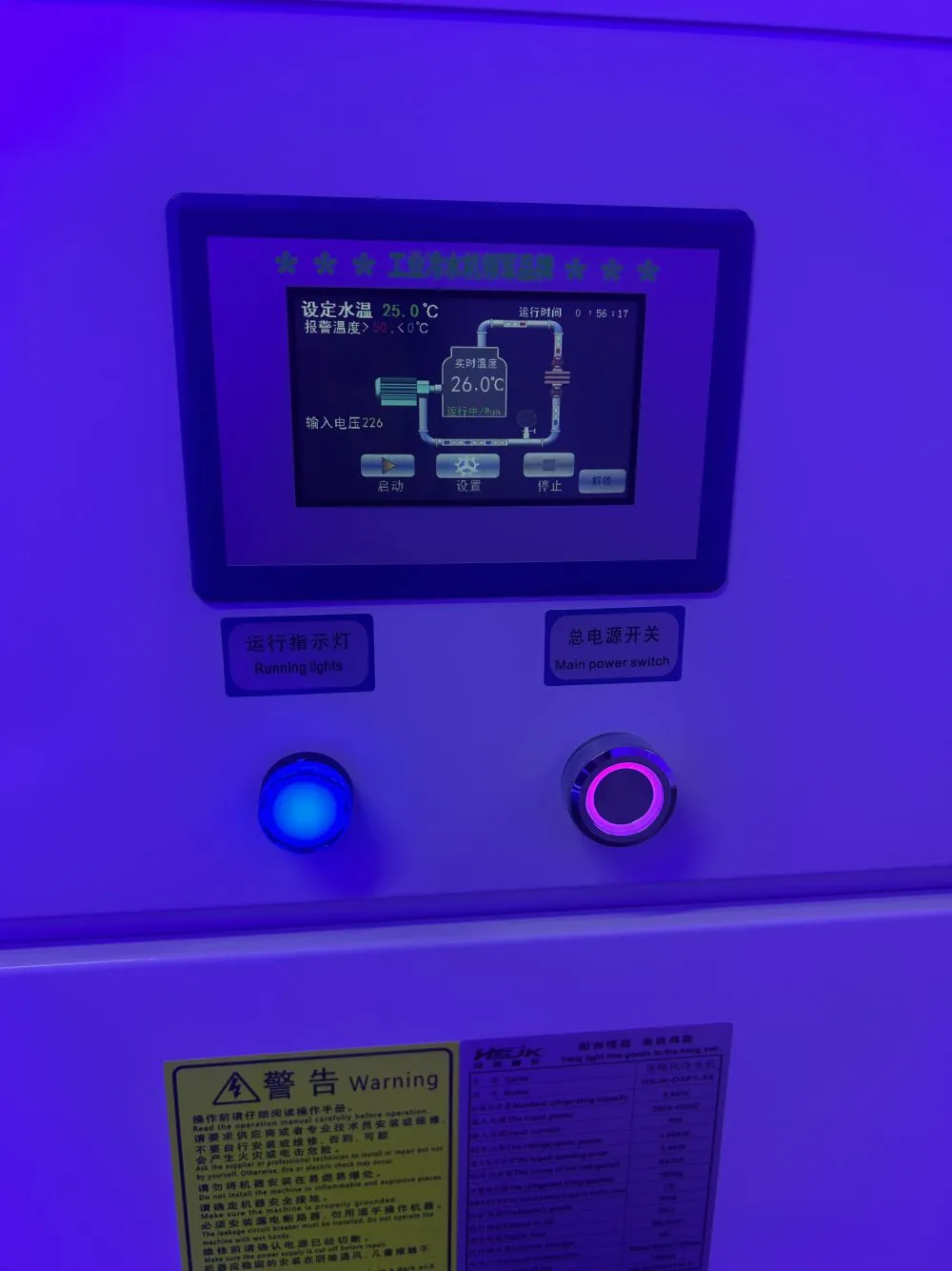
Moisture control applies wherever the line meets cell chemistry. Cooling circuits on a water-cooled head must be leak-tested and maintained, because a coolant leak onto a battery web is a serious contamination event. This is one reason cooling design and leak protection are specified as part of the equipment, not left to installation practice.
Electrical and ultraviolet safety follow the same rules as any industrial UV station: enclosed curing zone, interlocked access, eye and skin protection, and shielding that accounts for reflection off the moving metal web.
Equipment for a Battery Coating Line
The curing equipment on a web coating line has four requirements that follow from the process rather than from a generic lamp specification.
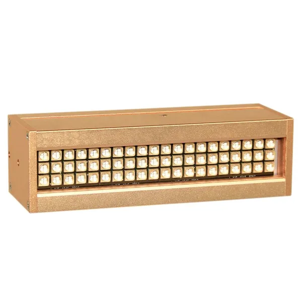
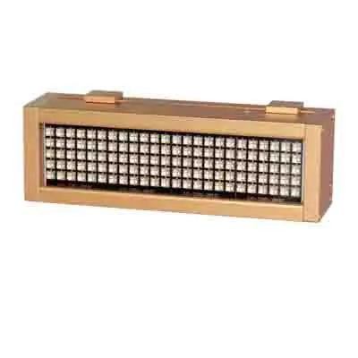
Web-matched width. The curing head must cover the full coated band uniformly, with heads arranged end to end where the web exceeds a single module length. Edge irradiance has to hold up to the same tolerance as the centre.
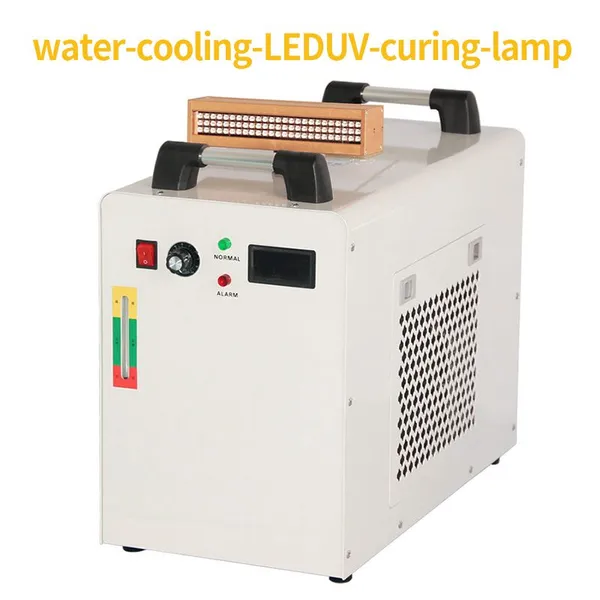
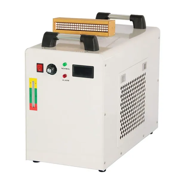
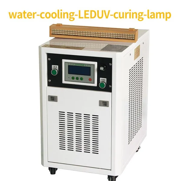
Continuous-duty cooling. A coating line runs for long shifts without stopping, and the emitter has to sustain rated output at that duty without thermal derating. Closed water cooling is the usual arrangement for high power density in a compact, continuous-duty head.
Matched wavelength. The source band must match the binder's photoinitiator absorption, and the choice is confirmed against the actual formulation rather than against a generic UV label. Where the line runs two binder chemistries, wavelength flexibility or separate heads per station matter.
Programmable, logged output. Intensity and exposure have to be repeatable per recipe and recordable per lot. A UV LED curing lamp with stable, adjustable output and accessible dose data supports the traceability file; a source without logging leaves the process dependent on operator memory.
Compact integration matters on an existing coating line, where space between coating head and winder is limited, and where any added station has to fit the web path, tension control, and exhaust arrangement already in place.
Common Defects and Their Usual Causes
Soft, tacky coating after cure. Oxygen inhibition, insufficient surface irradiance, or an under-cured formulation. Check surface intensity first, then inerting and formulation match.
Peeling or blistering after electrolyte soak. Weak interface cure on a porous substrate, usually from low interface irradiance or an over-thick filled film. Re-check depth cure on the actual electrode coupon.
Micro-cracks and flake on the winder. Over-cross-linked brittle film from excessive dose, or a binder grade too rigid for the flexible substrate. Reduce exposure and review the binder elongation.
Impedance rise or gas after cycling. Residual species from under-cure, or an over-thickened impermeable film. Compare soaked samples and residue checks against the validated recipe.
Uneven coating condition across the web. Irradiance falloff at the edges, an uneven wet film, or a head that drifted off the validated distance. Map irradiance across the width before changing formulation.
Localized under-cure after a formulation change. Changed filler loading or particle size altered scattering at the same settings. Re-validate the recipe rather than raising speed to compensate.
Conclusion
UV curing in lithium battery protective coatings works because it delivers low-temperature, in-line, low-residue conversion on a moving web, and it fails where the process is treated like decorative printing instead of electrochemical assembly. The film must convert completely at the interface, stay permeable to ions, survive electrolyte and cycling, and leave no species that contaminate the cell. Those demands define the irradiance, dose, wavelength, and cleanliness the cure station has to provide.
A UV LED curing lamp suited to this application delivers uniform energy across a full web width, sustains continuous-duty output under water cooling, matches the binder's absorption band, and keeps intensity and exposure repeatable and recordable. The rest is process discipline: film thickness and speed recorded together, an irradiance map across the web, soaked adhesion and electrochemical validation, and a recipe re-validated whenever formulation or geometry changes. Treated that way, the UV step becomes a controlled part of the battery interface that supports cycling life rather than a hidden source of later cell failure.
Recently Posted
-
UV Curing in Medical Device Assembly: Cured Is Not the Same as Validated
November 13, 2026Medical Devices Change What Curing Has to ProveIn most industrial assembly, a cured bond passes when it holds the part together. I Read More
-
UV Adhesive Curing in Automotive Assembly: A Structural Engineer's Guide to Bonds That Survive 15 Years on the Road
November 5, 2026Why Automotive Adhesive Bonds Fail in Places Nobody InspectsAutomotive assembly has quietly become an adhesive industry. A modern Read More
-
Finding the Real Process Window: How Top Printers Stop Guessing at UV Ink Curing
October 29, 2026Why "It Looks Dry" Is Not a Curing SpecificationWalk into any print shop and you will hear the same phrase: "the in Read More
-
UV Adhesive Curing Failures: A Process Engineer's Field Guide to Joint Strength, Shadow Zones, and Depth Cure
October 22, 2026Why UV Adhesive Projects Fail in Production — Not in the LabEvery process engineer who has specified a UV-curable adhesive has liv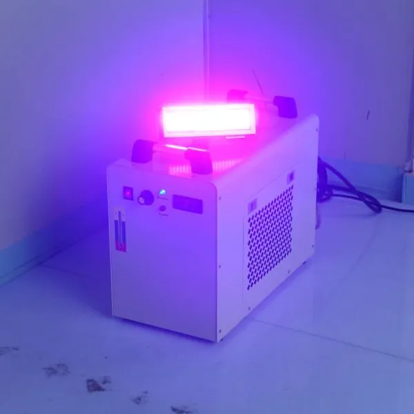 Read More

Contact Us
Recommended Products
-
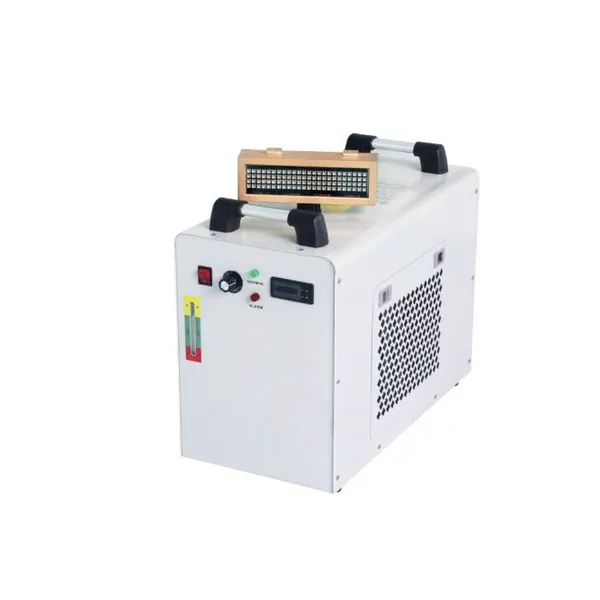
 Water-Cooled UV LED Curing Light Source, 365nm / 395nm Optional, High Power Industrial UV Curing System for UV Ink, Glue, Varnish CoatingNegotiableMOQ: 1 Combo
-
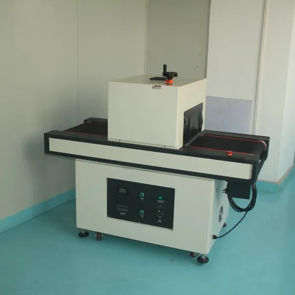
CT UV LED Conveyor Curing Tunnel | Water Cooled UV Curing OvenNegotiableMOQ: 1 Combo
-
CT2 LED UV Curing Light, Industrial UV LED Dryer for Ink, Varnish & Glue CuringNegotiableMOQ: 1 Combo
-
Youjiete CT4 Industrial UV LED Curing System, UV Curing Lamp for Printing & Electronic Bonding,365nm/395nmNegotiableMOQ: 1 Combo
-
Youjiete CT5 UV LED Curing Equipment, Water Cooling UV LED Light Source for Industrial UV Adhesive and Printing Ink CuringNegotiableMOQ: 1 Combo
-
Youjiete CT10 LED Curing Machine, Industrial UV Light Source for UV Ink, Adhesive & Coating Fast CuringUS$ 5000 - 10000MOQ: 1 Combo
-
Youjiete Large‑Area UV LED Surface Light Source Curing Machine, 365nm 395nm Customizable for Industrial UV Glue, Ink & Coating CuringNegotiableMOQ: 1 Combo
-
Youjiete Industrial LED UV Curing Tunnel Furnace, Belt Conveyor UV Dryer for Offset Printing, 365nm 395nm CustomizableNegotiableMOQ: 1 Combo
-
Youjiete Desktop UV LED Curing Tunnel Furnace, Conveyor Type LED UV Curing Machine for UV Adhesive, Ink, Coating DryingNegotiableMOQ: 1 Combo
-
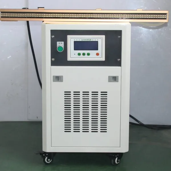
Youjiete Industrial Long Water‑Cooled LED UV Curing Lamp Head, UV Ink Curing LightNegotiableMOQ: 1 Combo
-
Youjiete LED UV Curing Lamp, Water‑Cooled UV LED Curing System For UV Ink, Varnish & Adhesive CuringNegotiableMOQ: 1 Combo
-
YJT‑CT4 Water‑cooled LED UV Curing Lamp 395nm Custom Size Industrial UV Ink Glue Curing LightUS$ 1520MOQ: 1 Combo
-
Power 1500w Led uv Curing LightNegotiableMOQ: 1 Combo
-
Green and Environmentally Friendly LED UV Curing MachinesUS$ 990 - 2000MOQ: 1 Combo
-
Advantages of Single Wavelength in LED UV Curing LampsUS$ 10000MOQ: 1 Combo
-
Is LED UV Harmful to Human Health?US$ 10000MOQ: 1 Combo
-
Advantages of Single Wavelength in LED UV Curing LampsUS$ 10000MOQ: 1 Combo
-
LED UV Curing LampUS$ 1980MOQ: 1 Combo
-
Green and Environmentally Friendly LED UV Curing MachinesUS$ 990 - 2000MOQ: 1 Combo
-
Green and Environmentally Friendly LED UV Curing MachinesUS$ 980MOQ: 1 Set