 Business License

UV Adhesive Curing Failures: A Process Engineer's Field Guide to Joint Strength, Shadow Zones, and Depth Cure
Why UV Adhesive Projects Fail in Production — Not in the Lab
Every process engineer who has specified a UV-curable adhesive has lived through the same disappointment. The bench test works: a clean glass slide, a generous bead, a 10-second flood of UV light, and a bond that survives a pull test with margin. Then the same adhesive goes onto a production line with mixed materials, hidden shadow areas, thicker bond lines, and parts moving at 600 units per hour. Suddenly the joint is soft at the edges, cloudy at depth, or fails the shear test during first article inspection.
The gap between lab results and production results is almost never the adhesive itself. It is the curing process — specifically, how well the light source delivers the right wavelength, dose, and geometry to every part of the bond line. This guide walks through the five most common failure modes I see in electronic assembly, optics bonding, medical device manufacturing, and glass furniture production, and the measurable fixes that resolve them.
The Photochemistry You Actually Need to Understand
Before troubleshooting anything, it helps to know what the light is doing. UV-curable adhesives contain three core components: oligomers that form the polymer backbone, monomers that adjust viscosity and cross-link density, and photoinitiators that absorb photons of a specific wavelength and decompose into free radicals. Those free radicals trigger polymerization, converting liquid into a solid cross-linked network in seconds.
Two parameters decide whether this reaction reaches full strength. The first is spectral matching: the lamp's output band must overlap the photoinitiator's absorption spectrum. Most industrial UV adhesives use initiators peaked at 365 nm or 405 nm. A lamp that outputs the wrong band — or a broad spectrum with low peak intensity at the target wavelength — will under-activate the initiator, no matter how long you expose the part.
The second parameter is energy density, measured in mJ/cm². A 0.1 mm bond line may fully cure at 200 mJ/cm². A 2 mm bond line with a translucent structural adhesive may need 1,500 mJ/cm² or more, because UV photons must travel through the adhesive itself to reach initiator molecules at depth. If the dose is too low, you get a "skin cure": the surface hardens, but the center stays liquid. That is the most common production failure I diagnose.
Failure Mode #1: Skin Cure on Thick Bond Lines
This is the one I see most often. A manufacturer bonds two transparent plastic housings with a 1 mm gap, hits the assembly with a flood lamp for 15 seconds, and the surface feels solid. A day later, the joint flexes under finger pressure, and a small pry at the edge reveals a soft, rubbery interior. The surface cured; the depth did not.
The root cause is photon attenuation. As UV light travels through the adhesive, it is absorbed and scattered. The top layer gets full intensity. The bottom layer gets whatever photons survived the trip. For adhesives filled with glass beads, silica, or UV-blocking pigments, attenuation is severe — a 405 nm lamp may deliver 50 percent surface intensity but less than 10 percent at 2 mm depth.
The fix has three parts. First, choose an adhesive formulated for depth cure, with photoinitiators that absorb at longer wavelengths where penetration is better. Second, increase total dose, not just surface intensity. A professional UV LED curing lamp with adjustable irradiance lets you run longer exposure at lower power to push photons through thick sections. Third, if the bond line exceeds 2 mm, consider a dual-cure adhesive that combines UV initiation with a secondary moisture or heat cure for shadow zones.
Failure Mode #2: Shadow Zones Behind Opaque Components
UV light travels in straight lines. This sounds obvious, but in production it causes endless failures. A PCB with a chip resistor behind the bond line, a glass lens assembly with a metal bracket blocking the light, a medical catheter hub with an RF shield — any of these creates a shadow zone where no UV photon reaches the adhesive. The joint looks cured from the accessible side. The shadow side remains liquid forever.
Engineers try rotating parts, adding side lamps, or extending exposure time. None of that works when a physical obstacle blocks the path. The correct solutions are structural. Design geometry so the bond line is visible from at least two angles. Use a dual-cure adhesive with a secondary mechanism (anaerobic, moisture, or heat) for shadow areas. Or specify a UV LED curing lamp with fiber-optic light guides that route light into confined spaces — common in medical device assembly where flood lamps cannot reach.
I once consulted on a head-up display bonding line where the shadow zone behind the LED array caused 18 percent field failures. The fix was not a brighter lamp. It was a re-designed fixture with four fiber-optic light guides aimed at each corner of the bond line, combined with a moisture-cure secondary adhesive. Shadow-zone failures dropped to under 1 percent in 30 days.
Failure Mode #3: Wavelength Mismatch Between Adhesive and Lamp
This failure mode is subtle because it does not produce an obvious defect. The adhesive cures, the joint passes initial testing, and bond strength is about 70 to 80 percent of spec. Over months, the bond creeps under thermal cycling, and the part fails in the field. Nobody traces it back to the curing lamp.
The cause is spectral mismatch. An adhesive formulated for 365 nm photoinitiators, cured under a 395 nm lamp, will partially cure because there is some spectral overlap. But the initiator is not absorbing at peak efficiency, so polymerization reaches 80 percent conversion and stalls. The bond is usable, but it lacks the cross-link density needed for long-term stability.
The fix is to verify spectral output before specifying equipment. Ask the adhesive supplier for the photoinitiator absorption curve. Ask the lamp supplier for the measured spectral output graph from a radiometer. The two curves should overlap at peak, not just at the edges. A well-engineered UV LED curing lamp outputs a narrow band centered on the target wavelength — typically 365 nm or 405 nm with FWHM of 10 to 15 nm. If the lamp's spectrum is a broad blue-violet blob, you are paying for off-band light that does nothing for the chemistry.
Failure Mode #4: Thermal Damage on Heat-Sensitive Assemblies
UV adhesives are often chosen because they do not require oven cure, which makes them attractive for heat-sensitive components: flexible circuits, thin plastic lenses, medical plastics that warp at 60°C, optical assemblies with index-matched gels. But a mercury UV flood lamp runs hot — surface temperatures at the lamp can exceed 600°C, and parts under the beam can reach 70 to 90°C during a 30-second exposure. That is enough to deform a thin polycarbonate lens or delaminate a flexible circuit trace.
The advantage of LED curing here is not energy efficiency — it is cold light. UV LEDs output virtually no infrared radiation, so part temperature rise during a standard exposure is typically 5 to 15°C, regardless of exposure duration. This means you can run longer exposures for deeper cure without cooking the assembly. For medical device and optics customers, this thermal advantage is often the deciding factor.
Always measure actual part temperature during cure with a thermocouple attached to the substrate. Do not trust ambient measurements — the lamp housing may feel cool while the part under the beam heats up from reflected heat or high-dose UV absorption.
Failure Mode #5: Poor Process Control Between Batches
The last failure mode is operational rather than technical. A line runs perfectly on Monday, produces soft bonds on Wednesday, and nobody knows what changed. The adhesive lot is the same. The fixtures are the same. The lamp output, however, has drifted. LED arrays decay gradually — roughly 10 to 15 percent output loss over the first 10,000 hours. Mercury lamps decay faster and less predictably. Neither decay triggers an alarm.
The fix is measurement-based process control. Install a UV radiometer at a fixed position in the line, and log irradiance at the start of each shift. When output drops 10 percent below baseline, flag it for lamp maintenance or calibration. I have seen shops reduce bond strength variation from ±25 percent to under ±8 percent simply by logging daily dose readings and compensating exposure time as the lamp ages.
A Practical 30-Day Validation Plan for New Adhesive Projects
If you are specifying a new UV adhesive and curing system for production, do not go straight to line build. Spend 30 days on bench validation. Week one: run a wavelength compatibility test — compare your adhesive under 365 nm, 385 nm, and 405 nm sources, measure bond strength at each, and pick the wavelength that gives the highest shear value. Week two: run a dose ladder on actual parts — vary exposure time in small increments, test depth cure with a microscope cross-section, and find the minimum dose that passes your strength spec. Week three: test shadow zones with typical geometry obstacles and verify whether secondary cure or fiber-optic delivery is needed. Week four: run thermal cycling and humidity aging on validated joints to confirm long-term stability.
By the time you approve the process for production, you will have data on wavelength, dose, shadow behavior, and thermal limits. That data removes the guesswork that causes 80 percent of field failures.
Bottom Line for Bonding Engineers
UV adhesive curing failures are almost always process failures, not adhesive failures. The adhesive chemistry is consistent. The light source, the exposure geometry, and the process control are where production lines lose strength, margin, and customer trust. Measure the dose, match the wavelength, design out shadow zones, protect heat-sensitive parts, and log lamp output over time. Do those five things and you will eliminate the majority of the curing defects that quietly drain profitability from bonded assemblies.
Recently Posted
-
The Complete Buyer's Guide to LED UV Curing: What Every Production Manager Should Know Before Upgrading
October 15, 2026Why This Guide Matters Before You Spend a Dollar on Curing EquipmentIf you have ever stood on a production floor watching ink dry Read More
-
CT10 LED UV Curing Lamp: Redefining Precision Industrial Curing Standards
October 8, 2026Introduction to CT10 LED UV Curing Core PositioningIn modern precision industrial manufacturing, stable, low-temperature and high-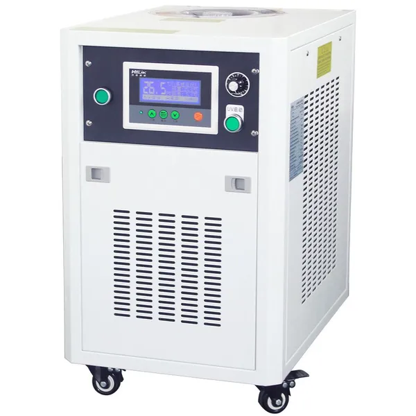 Read More
-
How leduvcuringlamp Transforms Modern Packaging Printing Curing Quality
September 28, 2026The Evolving Curing Demands of High-End Packaging ProductionToday’s packaging industry is shifting rapidly toward high-gloss finis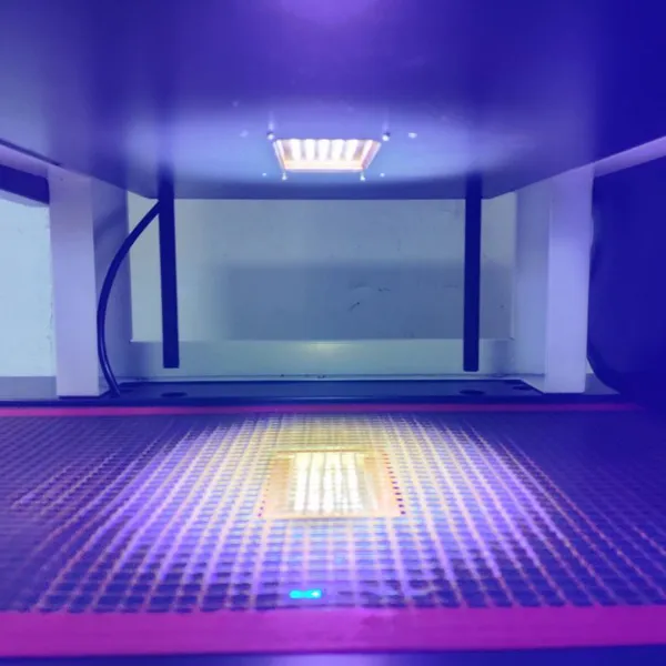 Read More
-
The Ultimate Guide to Stable UV Ink Curing With LED UV Technology
September 23, 2026Why UV Ink Curing Stability Determines Printing Product QualityUV ink printing has become the mainstream surface processing techno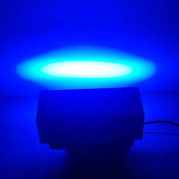 Read More

Contact Us
Recommended Products
-
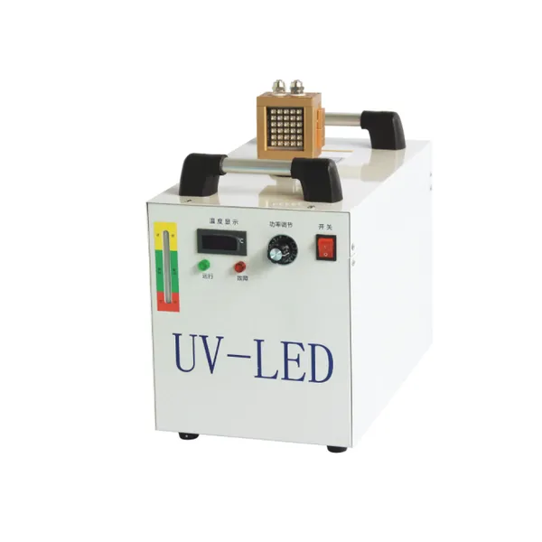
 Youjiete CT4 Industrial UV LED Curing System, UV Curing Lamp for Printing & Electronic Bonding,365nm/395nmNegotiableMOQ: 1 Combo
-
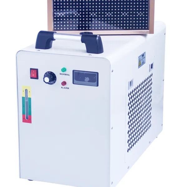
Youjiete CT5 UV LED Curing Equipment, Water Cooling UV LED Light Source for Industrial UV Adhesive and Printing Ink CuringNegotiableMOQ: 1 Combo
-
Youjiete CT10 LED Curing Machine, Industrial UV Light Source for UV Ink, Adhesive & Coating Fast CuringUS$ 5000 - 10000MOQ: 1 Combo
-
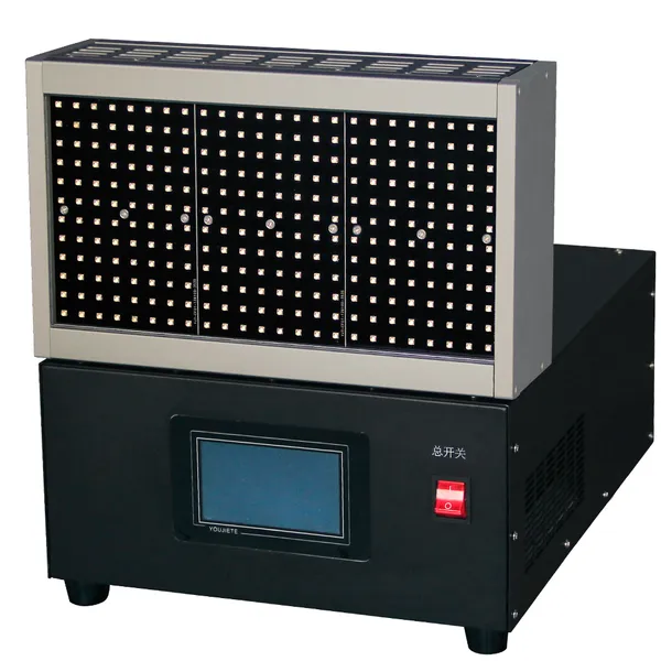
Youjiete Large‑Area UV LED Surface Light Source Curing Machine, 365nm 395nm Customizable for Industrial UV Glue, Ink & Coating CuringNegotiableMOQ: 1 Combo
-
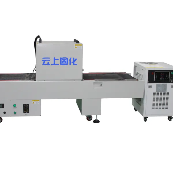
Youjiete Industrial LED UV Curing Tunnel Furnace, Belt Conveyor UV Dryer for Offset Printing, 365nm 395nm CustomizableNegotiableMOQ: 1 Combo
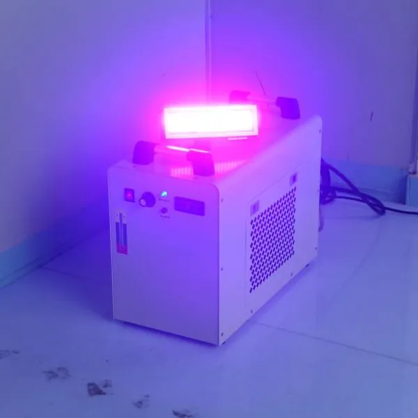
-
Youjiete Desktop UV LED Curing Tunnel Furnace, Conveyor Type LED UV Curing Machine for UV Adhesive, Ink, Coating DryingNegotiableMOQ: 1 Combo
-
Youjiete Industrial Long Water‑Cooled LED UV Curing Lamp Head, UV Ink Curing LightNegotiableMOQ: 1 Combo
-
Youjiete LED UV Curing Lamp, Water‑Cooled UV LED Curing System For UV Ink, Varnish & Adhesive CuringNegotiableMOQ: 1 Combo
-
YJT‑CT4 Water‑cooled LED UV Curing Lamp 395nm Custom Size Industrial UV Ink Glue Curing LightUS$ 1520MOQ: 1 Combo
-
Power 1500w Led uv Curing LightNegotiableMOQ: 1 Combo
-
Green and Environmentally Friendly LED UV Curing MachinesUS$ 990 - 2000MOQ: 1 Combo
-
Advantages of Single Wavelength in LED UV Curing LampsUS$ 10000MOQ: 1 Combo
-
Is LED UV Harmful to Human Health?US$ 10000MOQ: 1 Combo
-
Advantages of Single Wavelength in LED UV Curing LampsUS$ 10000MOQ: 1 Combo
-
LED UV Curing LampUS$ 1980MOQ: 1 Combo